Create an elevation profile
To view the elevation profile tool for 2D lines and 3D lines, you need to follow slightly different processes. Here’s how you can differentiate these processes:
For 2D lines
- Ensure you are in 2D mode by clicking on the 2D icon at the bottom left of the map.
- Select the Draw line tool and draw a line on the map at the required location for your profile.
- Your new line is stored in Places.
- Switch to 3D mode.
- Click the down arrow next to your new line to view the options for that place.
- Click Show profile using surface terrain.
- View the elevation profile along the line that was drawn; elevation values are taken from the base terrain dataset in the application.
- Hover over a point on the graph to view the elevation of that point along the line. Please note that for long, east-west lines, this point may appear offset from the drawn line due to the curvature of the earth. You can minimize this by adding more vertices to the input line.
- These steps can also be applied to view the elevation profile of lines added to places via a search option, using the identify tool or via a query.
For 3D lines
Lines drawn within 3D or 360 mode are now added as 3D polylines. The elevation profile tool is not supported for 3D lines but is accessible if the 3D line is reverted to 2D.
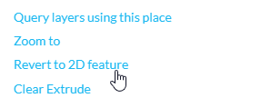
- To revert a 3D line to a 2D place, click the down arrow next the 3D line place.
- Select Revert to 2D feature.
- The line will now drape on the terrain and the Show profile using recorded elevation tool is now available for that place.
- Select the option to view the elevation profile.
- Previously, when lines were added to places in 3D and 360 view modes these were automatically draped the line on the ground. Please note that the elevation profile tool is also not available for a 3D line that has had the elevation mode altered to On the ground. The Revert to 2D option still needs to be applied to utilise the elevation profile tool.
Using 360 view mode
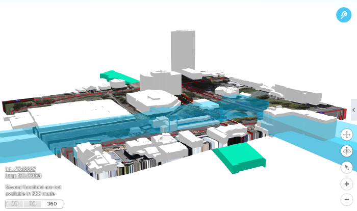
360 view mode launches a local scene at the current position of the map, presenting 3D data both above and below the surface of Queensland.
The controls while in this view are similar to 3D.
- Left click to pan
- Right click to tilt
- Mouse scroll to zoom in and out
360 mode is located down near the bottom left corner of the screen alongside the 2D and 3D view modes, and can be enabled once the icon lights up upon zooming in below a certain scale.
There are also the normal navigation tools available on the lower right side of the screen.
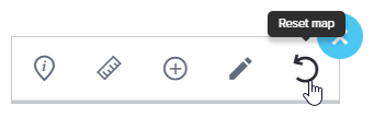
If you lose track of your local scene, you can navigate back to it through the drawing tools (in the top right), using the Reset Map button.
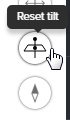
Or by clicking the Reset Tilt button (near the navigation tools down near the bottom right).
Please note that several functions are not available in 360 mode.
3D Places
Drawing places in 3D or 360 mode now utilises the sketch widget. This allows for the creation of places that have an elevation applied to them.
Please note that if places are drawn in 2D mode, when they are viewed in 3D or 360, they should continue to drape over the terrain.
3D places can be saved and shared in a map or included in a print. They can also be used in conjunction with the extrude tool.
Please note that 3D places can only be created using the point, rectangle, polygon and circle draw tools. Line, ellipse and text can be drawn when in 3D or 360 view but will be added as 2D places.
Create a 3D point
- Zoom to your location of interest and switch the view mode to 3D or 360.
- Open the toolbar and select the Draw places tool. Select the Draw point option.
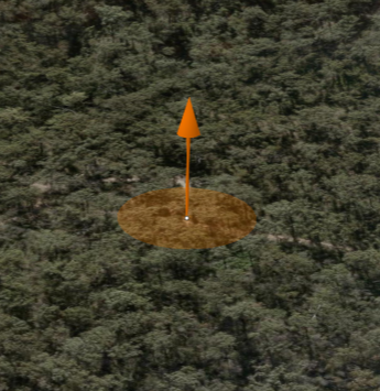
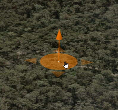
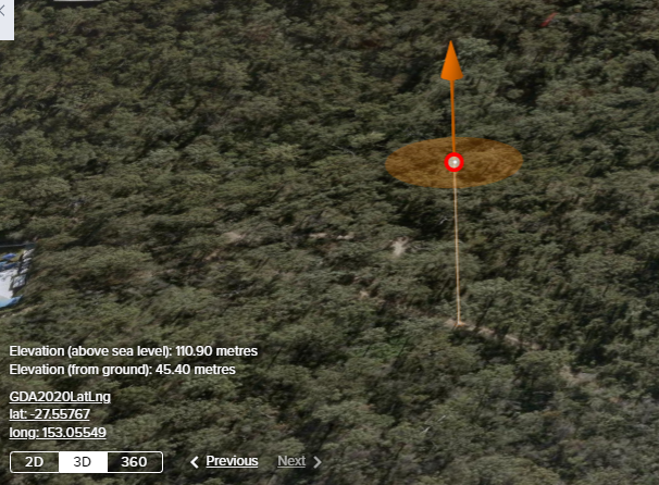
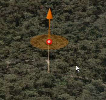
- Click on the map, an orange arrow and circle will appear around the proposed place, which will be highlighted red.
- Before accepting the place, you can adjust the placement of the point. Click and hold within the orange circle to move the point in an x or y direction.
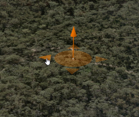
- Alternatively, the orange arrows allow you to limit the movement of the 3D point in a North, South, East or West direction.
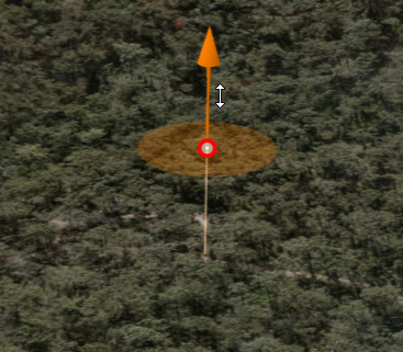
- Click and drag on the arrow to adjust the height of the point.
- The elevation value of the 3D point (both above sea level and relative to the ground) will be displayed in the bottom left corner of the map.
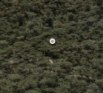
- Click outside of the orange circle to accept any changes you have made, and the point will be added as a place.
- Please note that the placement of 3D places can't be edited once they have been accepted.
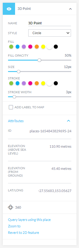
- Expanding the place will display the height above sea level and above the ground in conjunction with the latitude and longitude in the attributes.
- A label can be added to the 3D point once it has been created.
- The 3D point place can be opened in 360 mode or reverted to a 2D place but not extruded.
Create a 3D line
- Zoom to your location of interest and switch the view mode to 3D or 360.
- Open the toolbar and select the Draw places tool. Select the Draw line option. Please note that the 3D line can be rotated when using the drawing tools in 3D mode but once added as a place it can't be rotated when editing unless the view mode is 2D (due to current API limitations).
- Click on the map to start drawing the line, click to add more vertices. Double click to complete the line. Click and drag on the orange arrow to adjust the height of the line. The elevation (above sea level) and (from ground) will not be displayed in the bottom left corner of the map view, this is not supported for 3D lines.
- Please note that the elevation value provided is for the line as a whole, not the vertex selected.
- Additional vertices can be added to the line by selecting edit places.
- Please note that the placement of 3D places can be edited once they have been accepted in 3D mode.
- Click outside of the shape to accept any changes you have made, and the line will be added as a place.
- Expanding the place will display the height of the of the line (above sea level and above the ground) in the attributes.
- A label can be added to the 3D line place once it has been created. (There is a known issue with the label placement for 3D lines, the label may appear below the ground).
- The 3D line place can be opened in 360 mode, reverted to a 2D place or extruded. Please note that adjusting opacity is not supported for line features (due to current API limitations).
Create a 3D rectangle
- Zoom to your location of interest and switch the view mode to 3D or 360.
- Open the toolbar and select the Draw places tool. Select the Draw rectangle option. Please note that the 3D rectangle can't be rotated (due to current API limitations). Rotating the view prior to drawing the 3D rectangle will allow you to draw a 3D rectangle at an angle if this is required.
- Click and drag on the orange arrow to adjust the height of the rectangle. The elevation (above sea level) and (from ground) will be displayed in the bottom left corner of the map view. As the height of the rectangle is altered, these values will adjust accordingly.
- Click within the shape and the corners of the rectangle are highlighted with an orange point. If the corner point is selected, the height of that corner can be adjusted independently.
- Please note that the elevation value provided is for the centroid of the shape, not the vertex selected.
- Additional vertices can be added to the rectangle to convert it to a polygon.
- Please note that the placement of 3D places can't be edited once they have been accepted.
- Click outside of the shape to accept any changes you have made, and the rectangle will be added as a place.
- Expanding the place will display the height of the centroid of the rectangle (above sea level and above the ground) in the attributes.
- A label can be added to the 3D rectangle place once it has been created.
- The 3D rectangle place can be opened in 360 mode, reverted to a 2D place or extruded.
Create a 3D polygon
- Zoom to your location of interest and switch the view to 3D or 360.
- Open the toolbar and select the Draw places tool. Select the Draw polygon option.
- Draw a polygon and double click to close the shape.
- The drawn shape will be highlighted, and an orange circle and arrow appear in the centre of the polygon.
- Click within the shape and the vertices of the polygon are highlighted with an orange point. If a vertex is selected, the height of that vertex can be adjusted independently.
- Click and drag on the orange arrow to adjust the height of the polygon. The elevation (above sea level) and (from ground) will be displayed in the bottom left corner of the map view. As the height of the polygon is altered, these values will adjust accordingly.
- Click within the 3D polygon, hold and drag will allow you to adjust the location of the place.
- Please note that the elevation value provided is for the centroid of the polygon, not the vertex selected.
- Additional vertices can be added to the polygon, if this causes an overlap then this will create a hole in the polygon. Once extruded this becomes more apparent.
- If the height of the 3D polygon place is adjusted and a portion of the polygon is hidden, this means that portion falls underneath the terrain. If viewed in 360 mode the portion of the place that falls under the ground can be seen by adjusting the tilt.
- The 3D polygon place can be opened in 360 mode, reverted to a 2D place or extruded.
Create a 3D circle
- Zoom to your location of interest and switch the view mode to 3D or 360.
- Open the toolbar and select the Draw places tool. Select the Draw circle option.
- Click and drag on the orange arrow to adjust the height of the circle. The elevation (above sea level) and (from ground) will be displayed in the bottom left corner of the map view. As the height of the circle is altered, these values will adjust accordingly.
- A 3D ellipse can be generated by drawing a circle in 3D mode, then adjusting the extent of the shape to form an ellipse. If the Draw Circle checkbox is deselected when drawing in 3D or 360 mode it will be drawn as a 2D ellipse that drapes over the terrain.
- Click within the 3D circle and drag to allow you to adjust the location of the place. The size of the 3D circle can't be adjusted. If you click within the circle, vertices are highlighted orange. The location and height of these points can be edited at this stage, if required, to create a polygon that has a circular component. The height of each vertice can be adjusted independently. Please note that the elevation value provided reflects the centroid of the shape and not the vertex.
- Fill colour, opacity, and stroke colour and width can be changed prior to accepting the place.
- Click outside of the shape to accept any changes you have made and the circle will be added as a place.
- A label can be added to the 3D circle place once it has been created.
- The 3D circle can be opened in 360 mode, reverted to a 2D place or extruded.
Edit 3D places
The geometry of 3D places can now be edited once the place has been added to the Places panel. Open the Places panel, select Edit places then click on the place you wish to edit.
After selecting the place, a set of editing tools are now available for use. These tools may include move, resize, reshape or rotate. If individual vertices are selected, these can be adjusted independently also.
Depending on the type of feature and the available editing tools, you can edit the geometry of the selected feature in various ways. This may involve adjusting the height of the place as a whole, dragging vertices (x, y, z), adding new vertices, or reshaping the feature as needed.
After making the desired edits:
- Select Done to confirm and save your changes. This updates the geometry of the 3D place with your edits.
- Select Cancel to discard the changes you've made. This action will revert the place to its previous state.
Change elevation mode (Places)
- The elevation mode drop-down will only appear after Edit places has been selected.
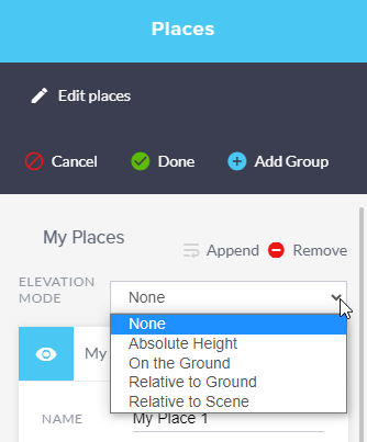
- Elevation mode is applied to the group of places, rather than individual places.
- When you create a new group and add places from different groups, each with its own elevation mode, conflicts can arise. The elevation settings from different groups may not blend seamlessly, leading to unexpected visual results. For example, one group may have relative elevation, while another has absolute elevation, causing disparities in how features are displayed.
- To avoid conflicts, try to apply consistent elevation modes within a group. If possible, ensure that places within a group have similar elevation characteristics or that they are intended to be displayed in a similar way.
Download 3D places
| File format | Place type | Download available | Symbology retained | Reimport available | Expected behaviour | 3D features display |
|---|---|---|---|---|---|---|
| SHP | 3D | ✔ | ✘ | ✔ | 3D features are reverted to 2D | ✘ |
| KML | 3D | ✔ | ✔ | ✔ | 3D features display; Symbology is retained |
✔ |
| JSON | 3D | ✔ | ✘ | ✔ | 3D features display; Reverts to default symbology |
✔ |
| CSV | 3D | ✔ | ✘ | ✔* | * CSV added as points display 3D features; CSV added as line or polygon display as 2D |
✔* |
Extrude
The Extrude tool is available for places that have been drawn in 2D, 3D or 360 mode (circle, rectangle, polygon and line features only).
The following outlines the behaviour of extruding polygons in the Queensland Globe.
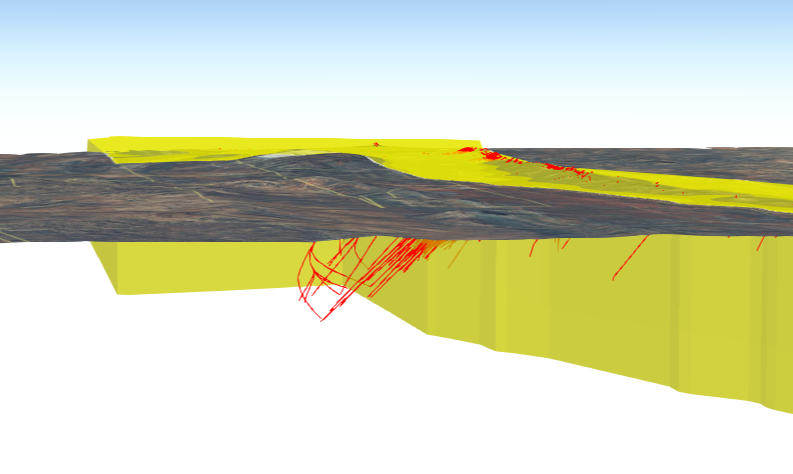
The extrusion can be applied in both above and below a place.
Any extrusions that extend below the ground surface can be viewed in 360 mode.
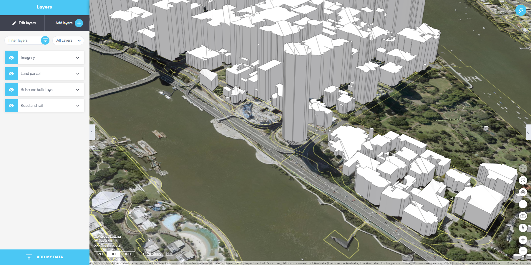
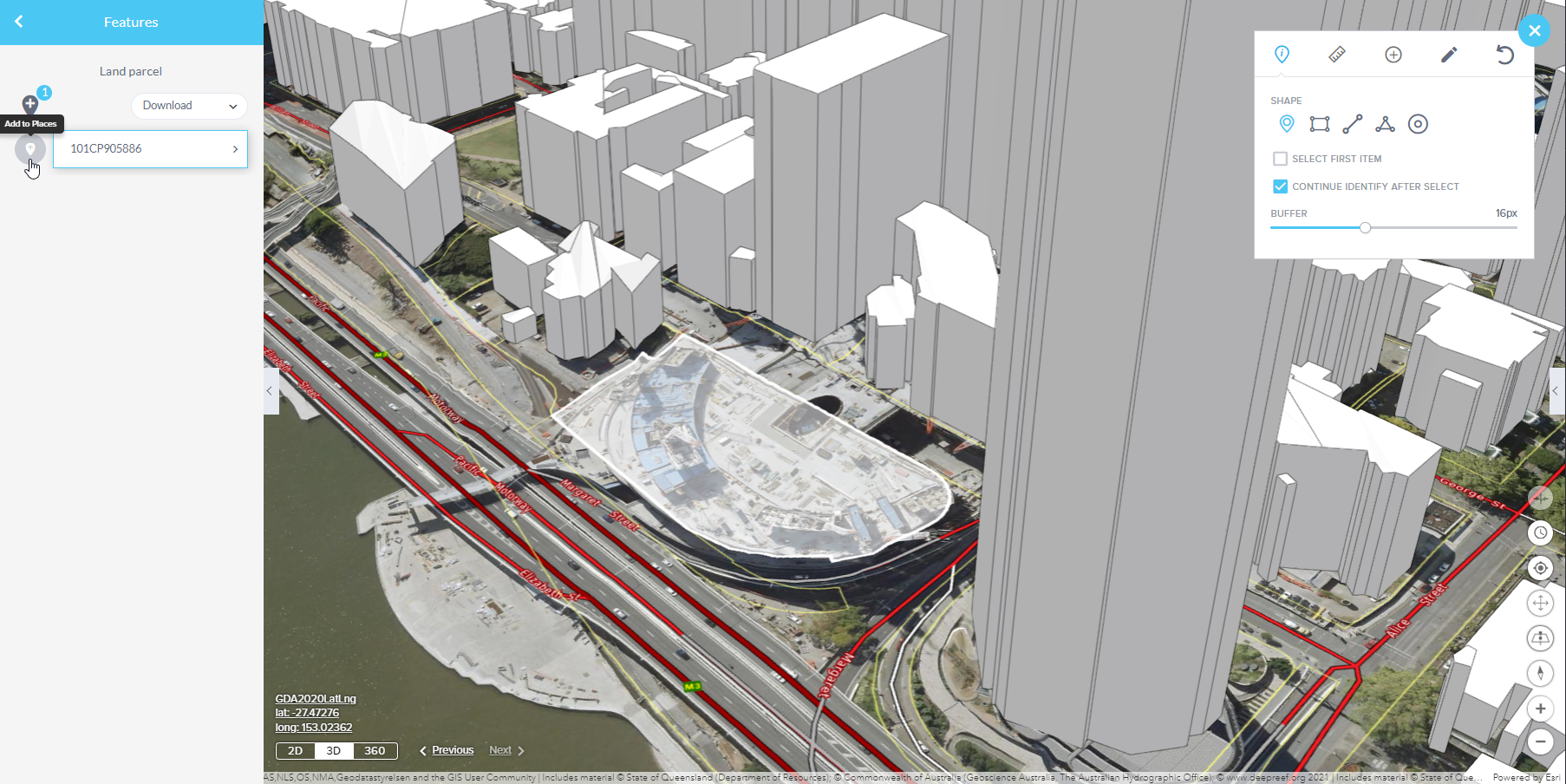
The extrude tool is also available for polygon places that have been added via the search tools (e.g. Lot on plan) or by using the identify tool on an added layer (e.g. Land parcel), where a polygon is returned.
To replicate this example:
- Add the Land parcel and Brisbane buildings layers to your map.
- Expand the toolbar and select the identify tool. Identify a parcel of interest and add it as a place.
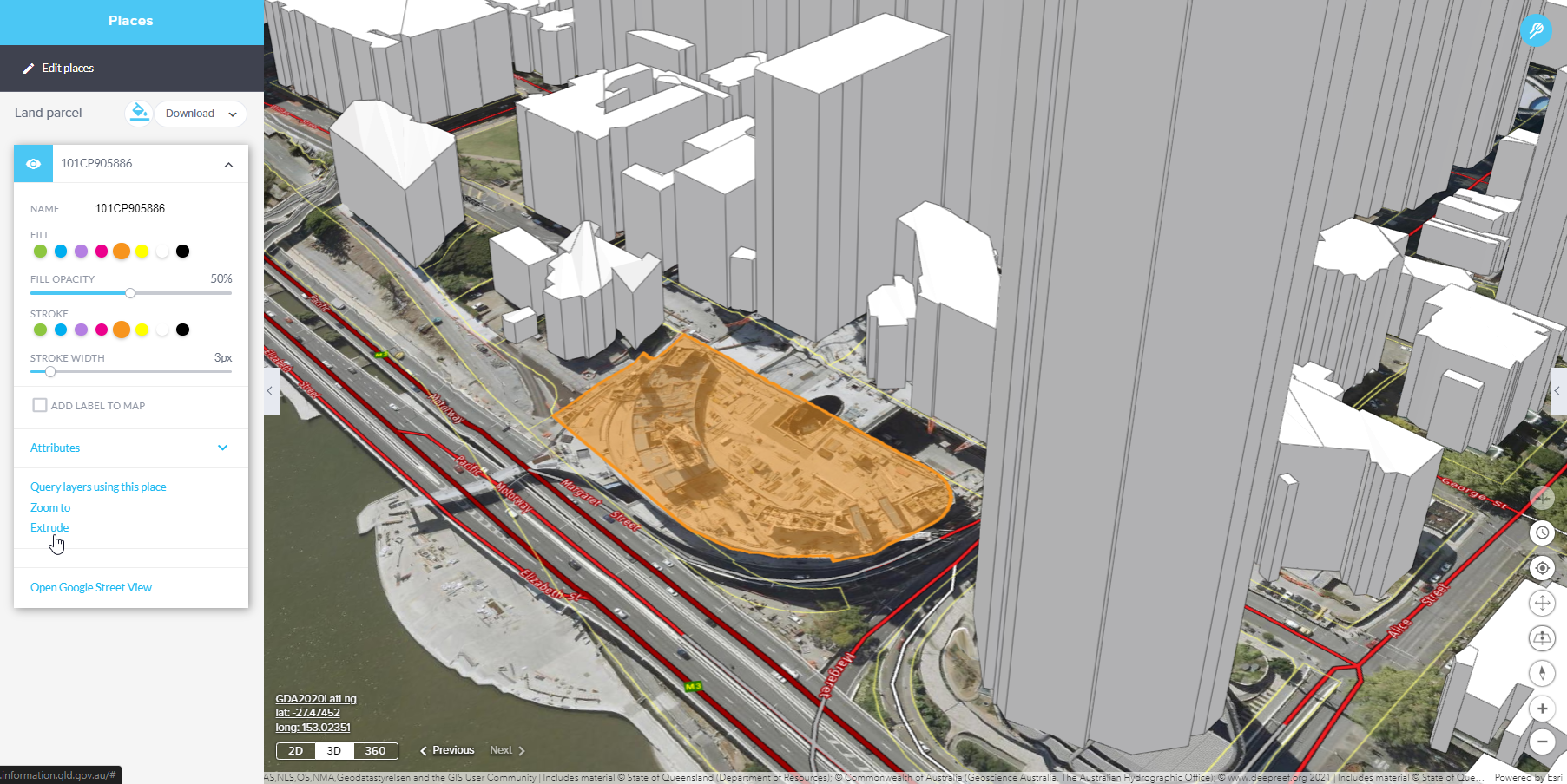
- Open the places panel, expand the place to change the symbology and select Extrude.
- The extrusion height settings can be adjusted to suit.
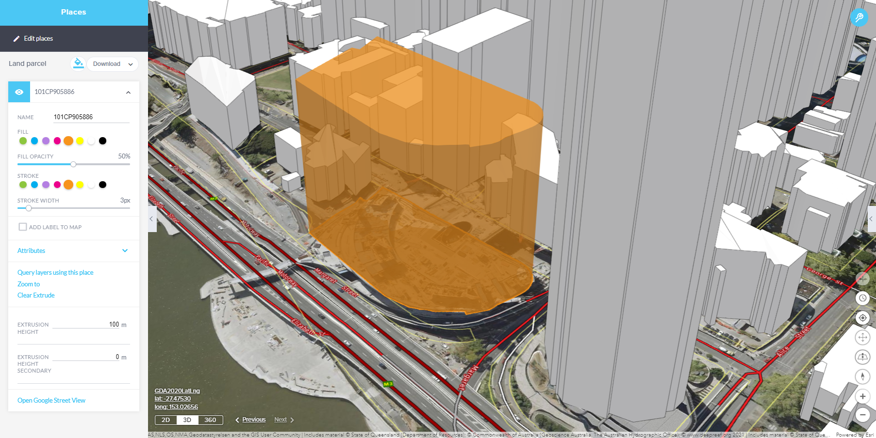
By default the extrusion height is set as 100m above and below the place. These values can be specified by the user.
The extrusion displayed takes into account the height of the vertices of the place. If the extrusion extends below the surface of the earth, switch to 360 mode to view the extrusion above and below the ground.
The opacity setting applied to the fill of a place also affects the extrusion associated with it.
In 3D and 360 modes, where 2D places are draped over the terrain, the extrusion displayed extends from each of the vertices.
It's important to note that the extrude tool is not supported for point or text places. Therefore, you cannot use the extrude tool to create extrusions for these types of place features.
Additionally, if you've added a label to a place, it will appear above the extrusion in the 3D or 360 view, ensuring that both the label and extrusion are visible to users. This arrangement helps provide context and information to viewers when working with 3D or 360 representations of geographic data.
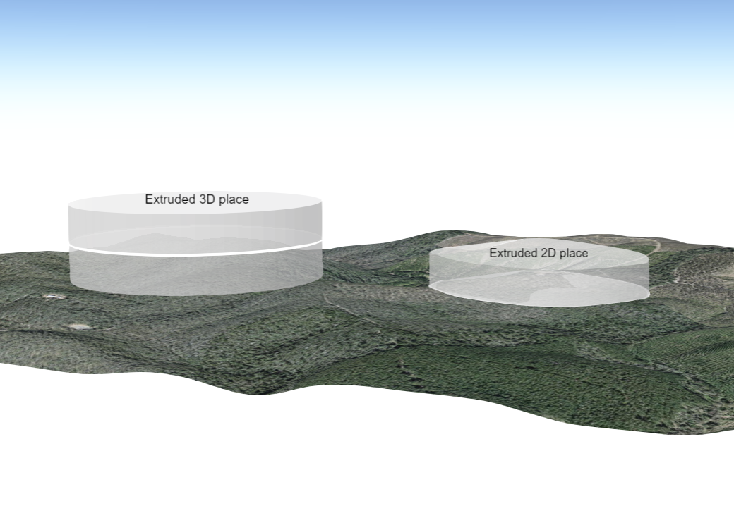
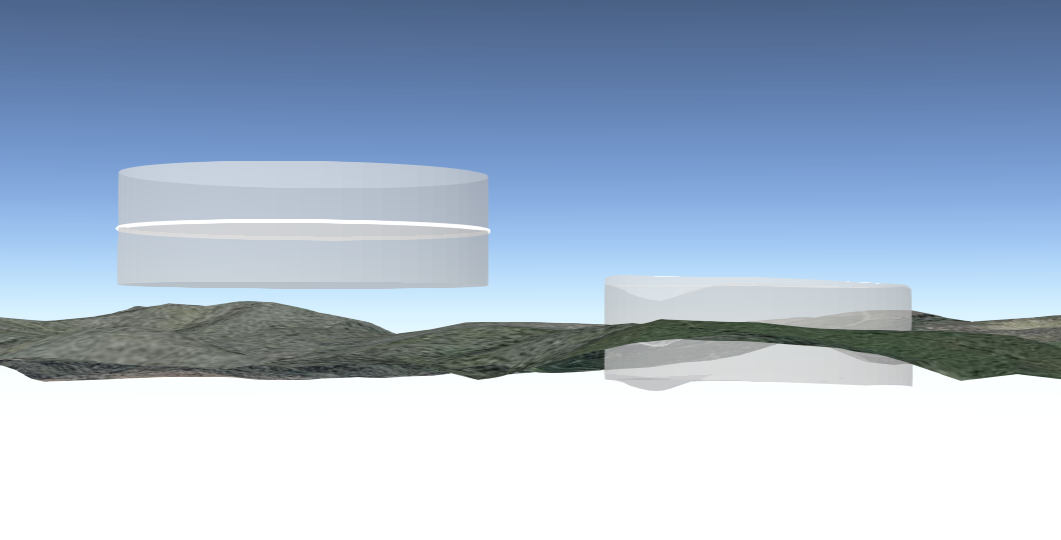
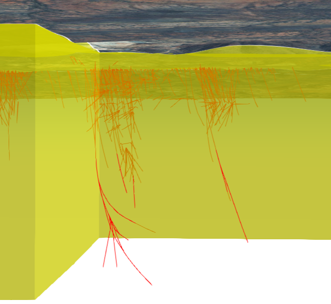
The following outlines the behaviour of extruding polylines in the Queensland Globe.
Extrude 3D Polylines
- When a polyline has been added in 3D mode, applying an extrusion will result in the extrusion being applied to the entire 3D place.
- This behaviour is suitable for representing three-dimensional objects that are meant to maintain their elevation variations along the length of the polyline, such as buildings or retaining walls.
Extrude 2D Polylines
- In situations where you want to extrude a polyline to depict features like a fence on a slope, it's advisable to first revert the polyline to 2D mode before applying the extrusion.
- Reverting to 2D mode likely flattens the polyline and ensures that the extrusion is applied in a way that does not consider the elevation variations of the original 3D mode.
- Additional vertices may need to be added to a line to ensure the extrusion takes into account the variations in the terrain.
This differentiation is important for accurately representing the intended features in your map. It allows you to have control over whether elevation information is preserved during the extrusion process or whether the extrusion is applied in a flat 2D manner. It's particularly useful for scenarios where you need to depict features like fences, which typically follow the contour of the land rather than being elevated.
When extruding a polyline, users can adjust the height and width of the extrusion. By default, the extrusion height for polylines is set to 30m, and the width is set to 5m.
If these values have been adjusted and the extrusion cleared, if the user chooses to re-instate the extrusion the application will remember the previously edited values for that place within the current session.
Variations in the extrusion result can occur with the following scenarios
- 3D lines added to a group that has the elevation mode of ‘On the Ground’.
- 3D lines drawn using the drawing tools in 3D mode, then ‘Revert to 2D place’.
- 2D lines viewed in 3D mode.
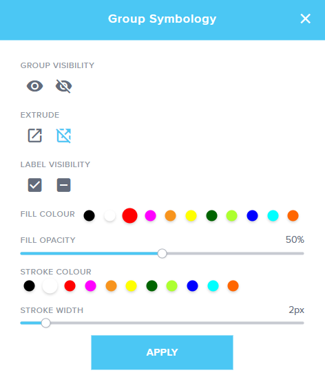
Extrude by group
When in 3D or 360 mode, the option to enable or disable extrusions has been included within the Group Symbology tool.
Enable extrusion: If extrusion heights have been applied to places individually, when this option is selected it will honour those extrusion heights. If any of the places have not previously been extruded the default extrusion height will be applied.
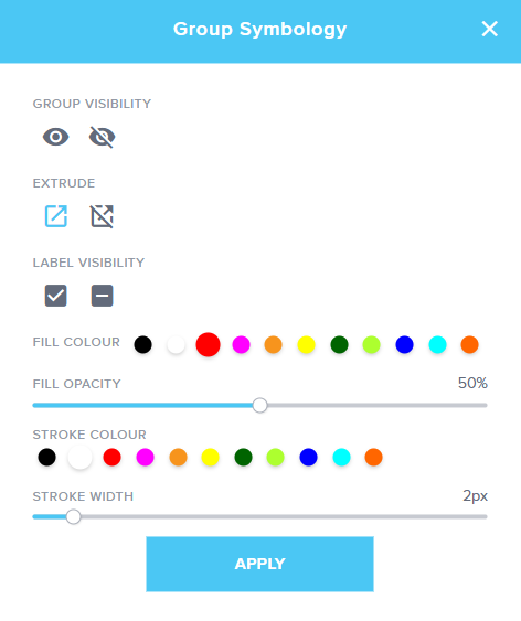
Disable extrusion: This option will clear all of the extrusions applied to a group of places.
It's important to note that you can still apply extrusions to individual places separately. These new extrusion options in the Group Symbology tool provide added flexibility when managing extrusions in your 3D or 360 scenes.
Please be aware that when you use the Group Symbology tool to enable or disable extrusions, the symbology settings will affect the entire group of places. If you have unique symbology settings for specific places within the group, using this tool will impact those settings.